1
16
submitted 11 hours ago* (last edited 11 hours ago) by EmilieEvans@lemmy.ml to c/3dprinting@lemmy.world

Next week is the FormNext 2024 trade show in FFM. Are you looking forward to visiting it or watching news coverage?

Looking into it I notice that this year there is a noticeable fluctuation. To name one example: Duet3D isn't there this year.

2
104
submitted 21 hours ago* (last edited 21 hours ago) by ExtremeDullard@lemmy.sdf.org to c/3dprinting@lemmy.world

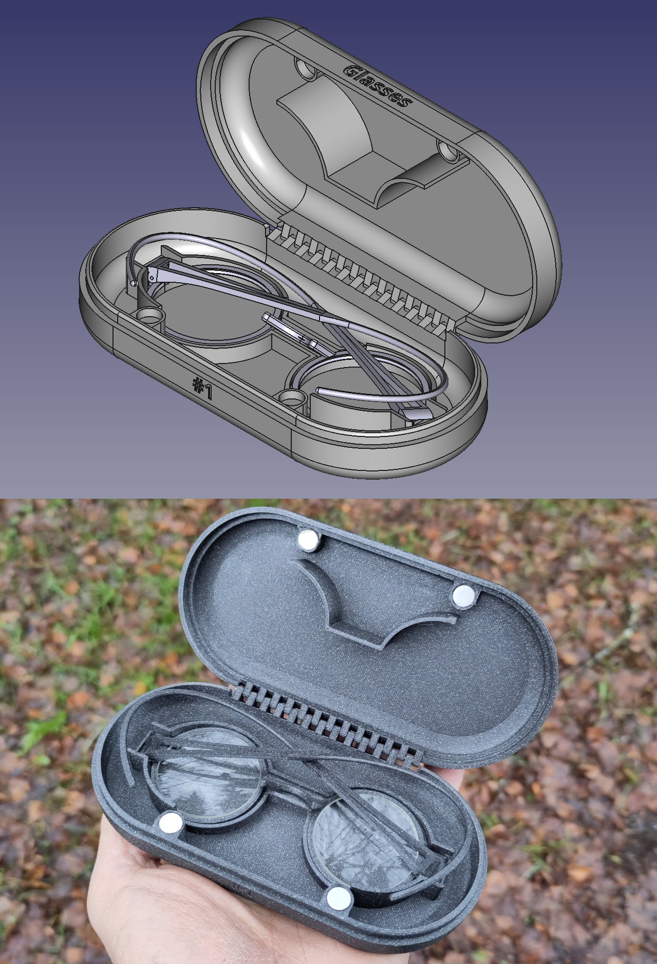
I made this custom case for my 3D printed spectacles:

Custom case

It holds the glasses by the edge of the frames, so the lenses are suspended above the bottom of the case without touching anything and no padding material is necessary to prevent scratching.

And being specially sized for those glasses, the case is no larger than it needs to be.

Did I mention that I love 3D printing? 🙂

3
9

This guy is doing amazing work, just wanted to share here. His videos are also quite humorous too.

4
41
submitted 1 day ago* (last edited 1 day ago) by Krauerking@lemy.lol to c/3dprinting@lemmy.world

So, I'm trying to print some older models from thingiverse and I have discovered that basically all the files I want to print have glaring flaws in them.

Internal free floating structures, connector pieces and holes that are the exact same size... So on and so forth...

Do I need to learn a software like CAD or Blender to fix these? I seem to be able to do some basic stuff in Orca Slicer but it honestly seems like as much of a pain to modify the parts there as it would be to use a real software.

Is there one that's easier? I think I messed around with SketchUp once upon a time.

I am worried this feels like opening a can of worms just so that I can make a thing that already exists in a dozen forms better.

5
79
PLA Print Degraded Over Time (discuss.tchncs.de)

This was an ornament I printed roughly 6 years ago. Being a Christmas ornament it spent most of those 6 years stored in my roof space.

Being in Australia this would have been subject to average temperatures of 30 to 35 degrees c but also peaks across summer approaching 70 degrees c. Also in high humidity.

The PLA crumbles into tiny pieces at the softest touch.

I thought it was interesting that PLA would start to break down in these conditions.

6
73
submitted 3 days ago* (last edited 1 day ago) by wfh@lemm.ee to c/3dprinting@lemmy.world

I was lucky to spend 4 beautiful years with a Creality Ender 3 v2 that I modded to the brim and never failed to deliver quality prints. I never had to adjust, calibrate or tweak anything regarding print quality.

I upgraded today to a Sovol SV-08 because despite its qualities, the Ender 3 is too small and slow for my current needs.

However, the print quality is definitely not there (yet). Overhang quality is bad but I think I may be able to tweak it with filament temp and/or cooling. There's a bit of ringing but I can live with it. My main issues are the large holes in the hull.

Filament: Overture black PETG, 240°C, 24min print.

What should I try?

Thanks

Edit: most issues were solved by doing the following adjustments:

  • PETG temperature increased to 245
  • volumetric flow reduced from 17mm^3/s to 10mm^3/s
  • manually adjusting z-offset with the paper sheet method like on my old Ender3

There are still minor issues like overhang drooping and adhesion needs a bit more work but quality is now almost on par with my previous printer.

Thanks to everyone !

7
23

Hello, all!

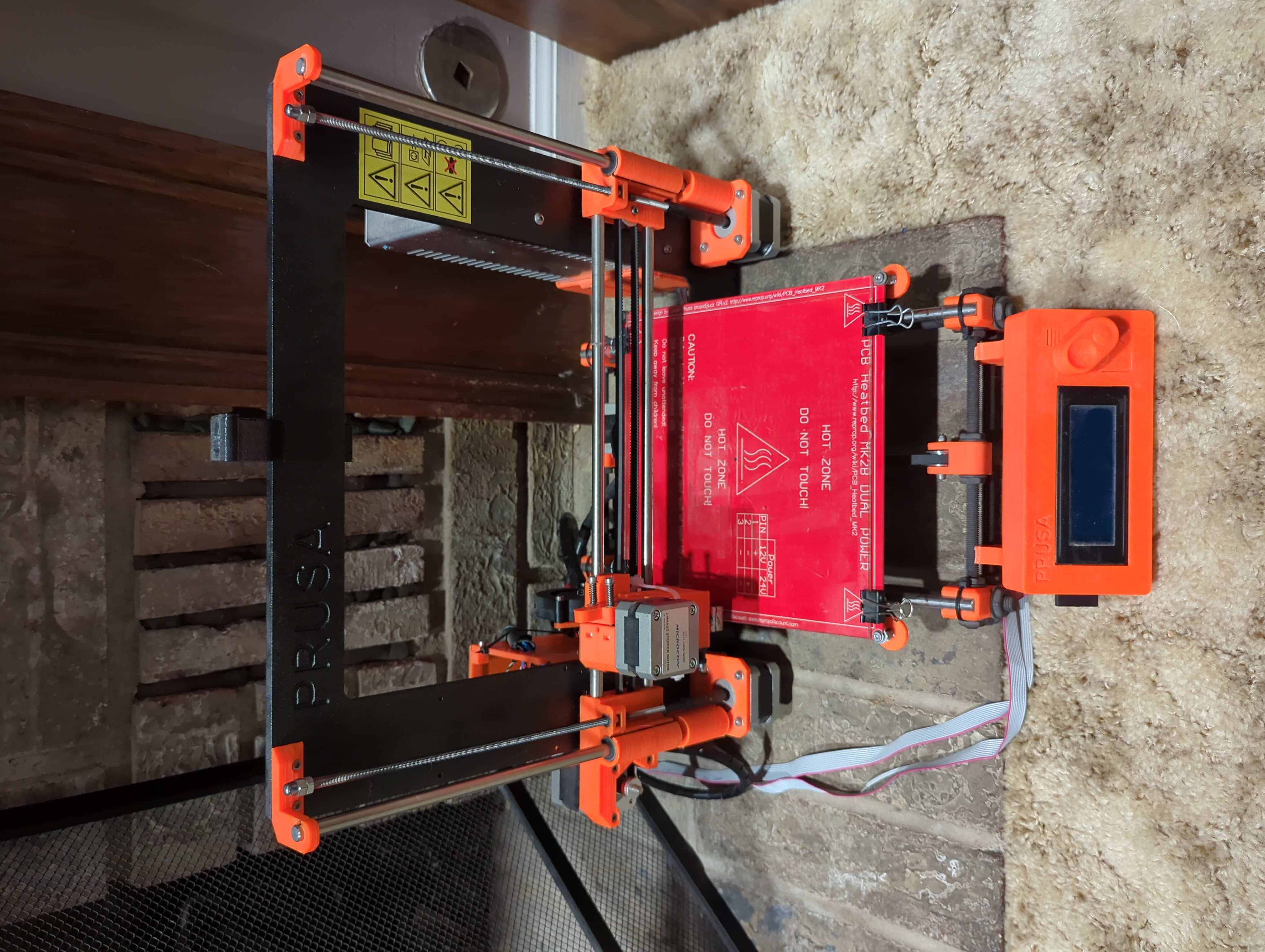
I have been given an old 3d printer and I know very little about them. I did manage to get it leveled/calibrated/running and did a test print with little to no problem. I'm told it is a Prusa i3 1.75mm (or a "MK1"), however searching for information about it beyond the original manual has been very difficult. Specifically replacement parts to print/buy.

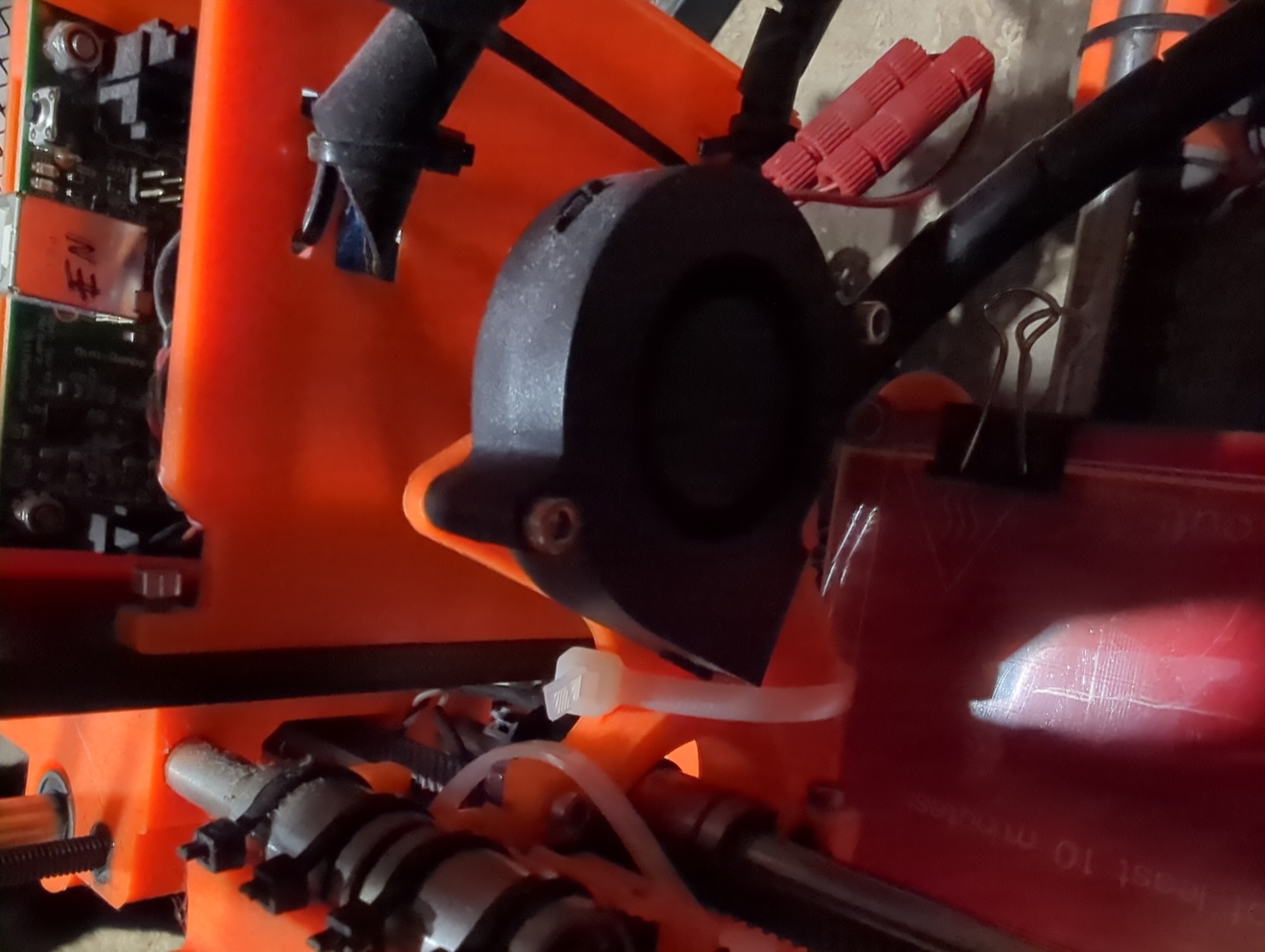
There is a fan on the back of the nozzle that has a shroud over it that has just absolutely snapped at some point. It's zip tied on at the moment and there's supposed to be a solid piece on the side but it has disappeared on me. I'd like to print another.

Does anyone know if this printer goes by other names or has an official model name? Everything I search up shows a bunch of MK2, MK3, etc. rather than this old thing. I'm also curious if anyone knows where I might find a model for that shroud.

Thanks so much!

Pics:

Printer

Fan

8
210
submitted 4 days ago* (last edited 4 days ago) by Excrubulent@slrpnk.net to c/3dprinting@lemmy.world

This is about a bad patent that is preventing slicers from making brick-layer prints that would increase strength enormously, despite the fact that there is clear prior art that has expired for nearly a decade. The patent is full of bad references to the prior art and clearly shouldn't have been approved - even if the person saying it isn't a lawyer, it's obvious.

The new bad patent from 2020 would keep the invention away for another 20 years, and do real harm to the development of 3d printing.

The creator asked viewers to share this with people in the FOSS slicer community. I don't know if that's anyone here, but lemmy is pretty FOSS-happy. Also the FOSS communities here might be interested to hear about how this patent is hamstringing development of FOSS features. I don't have the time right now to search through the communities so any crossposts would be welcome.

9
9
submitted 2 days ago by Sparky to c/3dprinting@lemmy.world

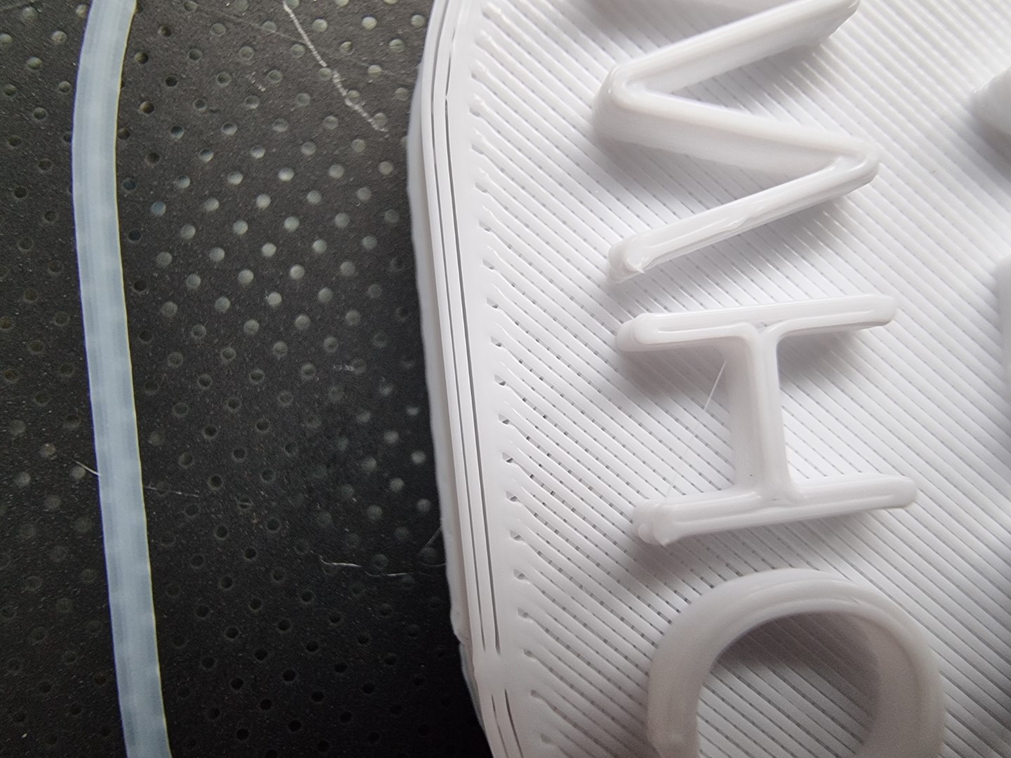
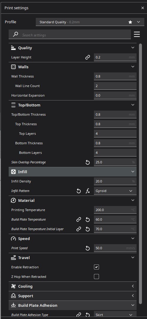
Hey y'all, I've been having issues with gaps forming between the outer layers of the print walls, and I'm not sure how to fix that. I thought it might be because of a clogged extruder, but the issue didn't get fixed when I cleaned it. I tried adjusting the E-steps, but smaller values caused blobs of filament to form on the outer walls likely because lower values overextruded the filament. Apart from the weird top layer and walls, the prints turn out perfectly fine, so it might be a slicer related issue. The printer is an Ender 3 pro with a bltouch sensor and upgraded marlin board + octoprint.

Here are some pictures of the issue, and a screenshot of the slicer settings:

Any help is greatly appreciated :3

10
18

Klipper aborted the print with:

Heater extruder not heating at expected rate Transition to shutdown state: Heater extruder not heating at expected rate See the 'verify_heater' section in docs/Config_Reference.md

Before any of this started,I goobered my original Rapido, so I replaced it with a Rapido 2. It's been in the printer since April, but I haven't done a ton of printing with it. After the replacement, all was well for a while. At some point, Klipper started randomly tripping thermal runaway protection. The spikes were instantaneous, so I suspected a wire break. It wouldn't be my first and they're usually easy to find. I moved the tool head around trying to find it with no success. I pulled apart both cable chains (yay Voron) to look for the wire break and didn't find one. I flipped the printer updside down and connections at the MCU - everything was fine. I went through the hot end and inadvertently pulled the thermistor out of the m3 slug. Here's a stock photo:

Suspecting a potential wire break at the thermistor, I manipulated the wiring to no real effect. Inside the M3 bung was some dried white stuff, which I think was probably Boron Nitride Paste. I bought some more from Slice Engineering and reinstalled the thermistor.

Two things changed after this. First, the terminator seems to be reading lower than it did before. I say this because I have a ton more stringing than I did previously. Second, the temperature is no longer spiking but it is doing this high frequency oscillation thing now.

The oscillation only happens once the printer is moving quickly. If it's still, or moving slowly, things are fine.

Thoughts? I'm suspecting the thermistor, but would like to troubleshoot if possible vs just throwing parts at the printer.

11
43

Consider watching this video with FreeTube, a nifty open-source program that lets you watch YouTube videos without Google spying on your viewing habits!

Combined with Libredirect, which automatically opens youtube links in Freetube, it becomes really slick and effortless to use.

12
30

Any thoughts on this. It seems pretty obvious as a development once you get into it and there doesn't seem to be much difference between the new patent and the expired patent. Layer adhesion is the big Achilles heel of 3D printing after all.

13
41

I find after this election that I have an unexpectedly pressing need to wave large obnoxious flags from my sensible fuel-efficient subcompact while I drive.

Has anybody got models, templates, suggestions for how to mount a stout pole to a hatchback? I’m thinking of some kind of tube on a short arm that I could close the rear passenger door or the cargo door on to hold it in place.

14
78

You might recall last month that I posted about my 3D-printed spectacles.

Enough people asked me for the files and for details on how to order lenses and mount them into the frames that I figured I'd release everything with instructions - and also redesign the hinges a bit so the temples fold more compact, something I meant to do for some time.

15
34
Can I salvage this? (lemmy.blahaj.zone)
submitted 1 week ago by Interstellar_1 to c/3dprinting@lemmy.world

The filament came out during a print and I don't know what layer it came out at. I've spent a lot of filament on this print, so is there any way to continue it?

16
17

I have a Steam Deck, Switch lite with grip, Anbernic 351v, and Gameboy advance (The non clamshell one) that I want to store in my drawer, but also want to keep them tidy, well displayed, and unharmed at the same time.

I was thinking to 3d print insterts/molds of the consoles that I can just slip them in and out of, and was wondering what the easiest way to accomplish that would be.

Also, I tried to upload pictures but kept getting an error.

17
53
submitted 1 week ago* (last edited 1 week ago) by callcc@lemmy.world to c/3dprinting@lemmy.world

cross-posted from: https://lemmy.world/post/21641314

I'm designing a case for a dew-point ventilator controller to be 3d printed. The controller is implemented using arduino on an esp32. The project is based off of the code and HW implementation by Make Magazine Germany: https://github.com/MakeMagazinDE/Taupunktluefter. When starting out I was thinking this would be an easy project but it turned out that especially the lid with its lip and groove design and the parts fixations were not that easy. I'm excited to finally print it.

The file is parametric to some extent and the main footprint is based off of a master sketch. Many parts were imported as step files from grabcad. I used FreeCAD 1.0-rc1 which works like a charm for many things. Next thing I would like to do is to use the new assembly workbench. What do you think?

Manual "Exploded view",

Opaque view.

EDIT: I didn't mention the most important part. The device switches on a ventilator when the absolute moisture content outside is lower than inside a a certain room. This results in drying of the room that you ventilate like a basement with moisture issues. The dew-point acts as a proxy for measuring absolute moisture content.

18
85
submitted 1 week ago* (last edited 1 week ago) by ExtremeDullard@lemmy.sdf.org to c/3dprinting@lemmy.world

You might find this little tool useful:

3D-printed holes gauge block

This is a block with a series of vertical and horizontal holes from ⌀1 mm to ⌀3.6 mm (nominal) in 0.1-mm increments. I print this block with any new printer / new material at the layer thickness and speed I use most often and keep the blocks as references.

Then, when I want to print a part with a hole in it that will end up printed at the final diameter without any rework (or very close, but usually it ends up exactly right) I use the gauge block I printed with the printer and the material I intend to print the part out of to find out which nominal diameter hole I need to use in the model for the hole.

For instance, the block in the photo was printed on a Prusa Mk4 with PLA at 0.2 mm layer thickness. If I want a ⌀0.8-mm vertical hole with no interference in my final part in PLA out of that printer, I'll need to model a ⌀1.2-mm hole. I know that because the shank of a 0.8-mm drillbit will slide freely in the vertical hole marked ⌀1.2 in the block.

Or if I want a hole that I can screw an M3 screw into without having to run a tap through it, the block tells me I would have to use a ⌀3.2-mm hole to fit a ⌀3-mm pin in freely, and I back off 0.4 mm to get a hole in which the screw thread will engage well but reasonably lightly, or 0.5 mm for a tighter engagement (but with a bit more risk with horizontal holes near an edge, because the layers might separate) so I know I'll have to model a ⌀2.8 or ⌀2.7 hole in the model.

I use those gauge blocks all the time. They save me a lot of time on parts that I print often because I never have to ream or thread the holes: they come out the printer just right and ready to use.

19
17

I recently got back into 3d Printing because it finally seemed like it had matured into a usable production method - where one could actually just make parts instead of spending all their time fiddling with the printer. That said, I realize there are still some benefits to some fiddling.

I'm wondering about other's process using the calibration prints in Orca. Do you go beyond maybe a temp tower, flow rate and pressure advance? Do you do those in any particular order? Bambu owners, do you bother on Bambu filament, or do you find their stock settings are pretty close (I haven't been bothering - most of it seems to do pretty well without).

I started thinking about this because I pulled out some OLD filament when I got my X1C, just to see if any of it was still usable. I dried it all thoroughly with a dehydrator, and have been pleasantly surprised. Much of it has been fine. The really old ABS has been fine as was the slightly newer ASA. The 5-year-old Hatchbox PLA was perfect, but a slightly newer generic PLA roll is terrible (it may have been bad when new). Old PETG has been hit and miss. I had all but given up on one roll, only to try tuning it, and suddenly got usable prints for the rest of the roll. Then the next roll clogged the nozzle on the pressure advance tower. I could just toss it all, but it was already paid for several years ago, so anything good that comes out of it is a win.

20
14
submitted 1 week ago* (last edited 1 week ago) by Linsensuppe@feddit.org to c/3dprinting@lemmy.world

Hi, I have printed a small holder for a Bowden tube to print from my filament dryer outside of the enclosure, but the filament coming out of the tube is tensioned and I don’t know if it will cause problems later. Is this fine to keep or how can I fix this? This i a Ender 3 V3 SE btw.

21
29
PLA living hinges (toobnix.org)

This is the worst possible setup to print living hinges: PLA isn't terribly flexible, and here the flexible bits have to be printed vertically, which really isn't ideal to withstand cracking.

Yet when the application isn't heavy-duty like in this clamp-on connector, even PLA printed "against the grain" works well too: this connector can spread its hooks linearly 3 mm apart and the living hinges don't crack or weaken even after many cycles.

22
174
submitted 1 week ago* (last edited 1 week ago) by the16bitgamer@programming.dev to c/3dprinting@lemmy.world

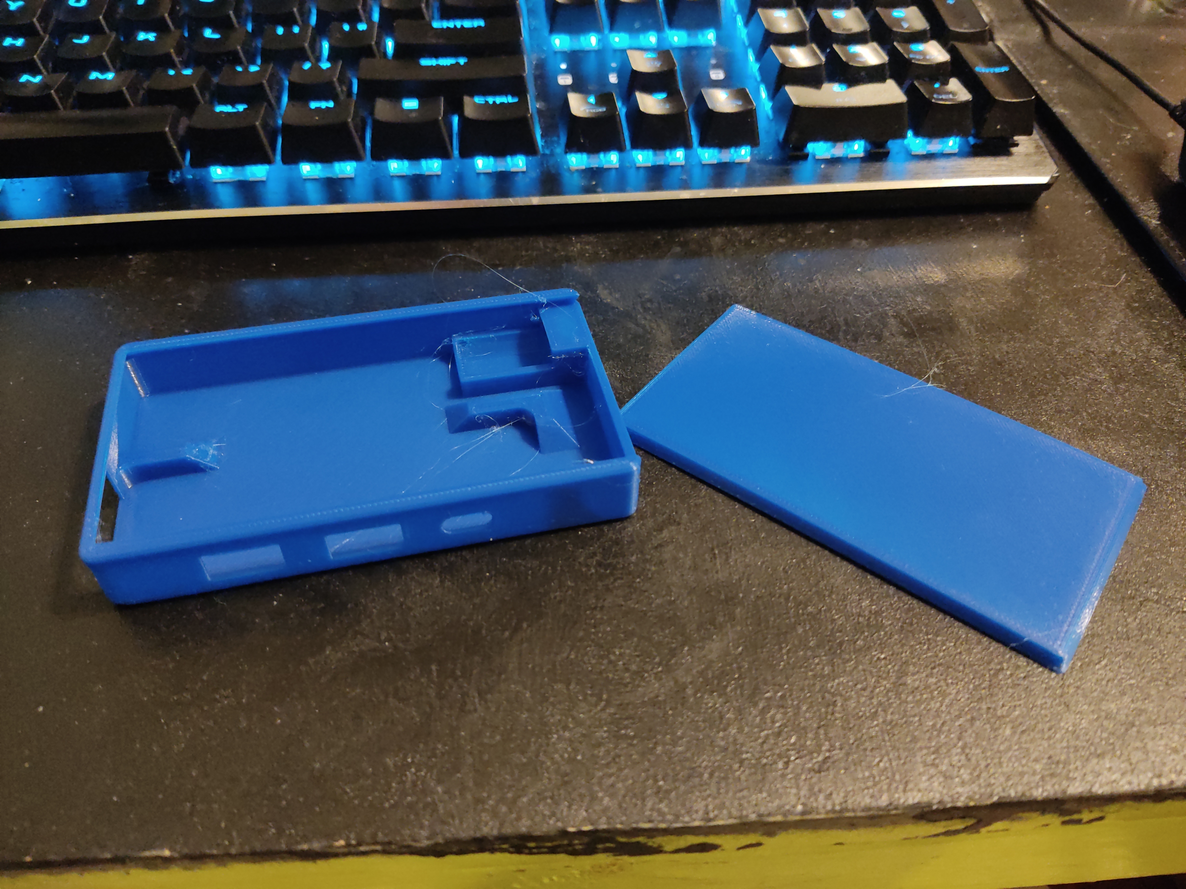
So my trusty USB-C Dongle which I use to connect my switch to a TV on the road is dying. The cable has frayed and I don't want to touch it any more.

So I decided to turn it into a USB-C Hub... basically give it a shell to hide away the cable.

Designed the part in FreeCAD in 30 min, and BOOM

Needed to do a bit of a redesign after the first print, what you see here is the V2. The Lid slides on and the USB-C to C female connector is slotted in. Needed to heat it up to get it to fit.

But I am very pleased with the design. Works well (now the slots are bigger. And I can safely throw it into a bag without risk of self destruction.

Sure I do need more cables but this also means I can upgrade/replace cables when they ware down.

5/7 would recommend!

23
30
submitted 1 week ago* (last edited 4 days ago) by HumanPenguin@feddit.uk to c/3dprinting@lemmy.world

EDIT: Update and pic in comments:

Hey folks. I posted a while back asking for some advice on a future purchase.

To sum up. My brother and I are visually impaired and retired through that.

We have purchased a tiny 25ft narrowboat between us we use to travel around the UK.

And as our vision is getting worse (we will likely lose it eventually). I have some major electrical work planed this year to make thing easy for us to maintain.

So I was looking for advice on nylon printing. Yep it has to be nylon. Because some of this stuff needs to sit over the tiny hot engine plus alternator and survive diesel splashes amd bilge water etc while supporting electronics.

But some here also pointed out petg will work when. The heat is less high. So thanks.

This is just an update that i have just had the printer etc delivered.

I have a Neptune 4 pro with a tent and vent system to keep temprature and fumes safe stable.

I have a 70c filament dryer and plan to print Descicant hokder to be placed in spools with lids that hold hydrometers. This and some vacuum bags should allow storing the petg and nylon easyer. Then Microwaving the stuff when the meters are above 25%

Also those desicant holders look worth adapting somehow for the boat.

So now I need to replan my workshop to make setting all this up and using it easy vision wise. That will take a good few days.

This is basically a thank you for your help in the past and a "Hi ill be posting the mess I make learning how to get this workjng over the next few months. "

Thanks guys all the best

24
33
submitted 1 week ago by j4k3@lemmy.world to c/3dprinting@lemmy.world

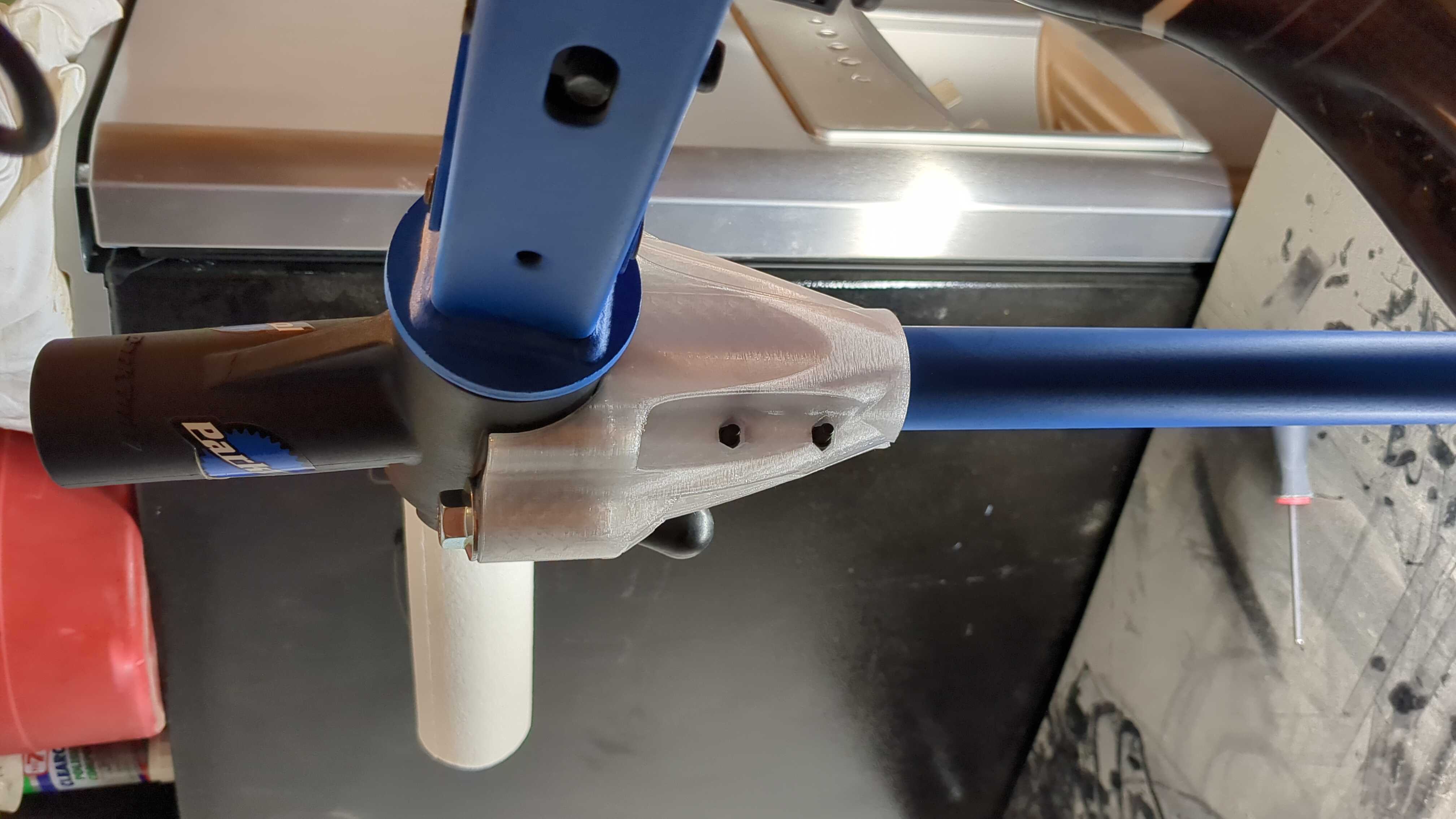
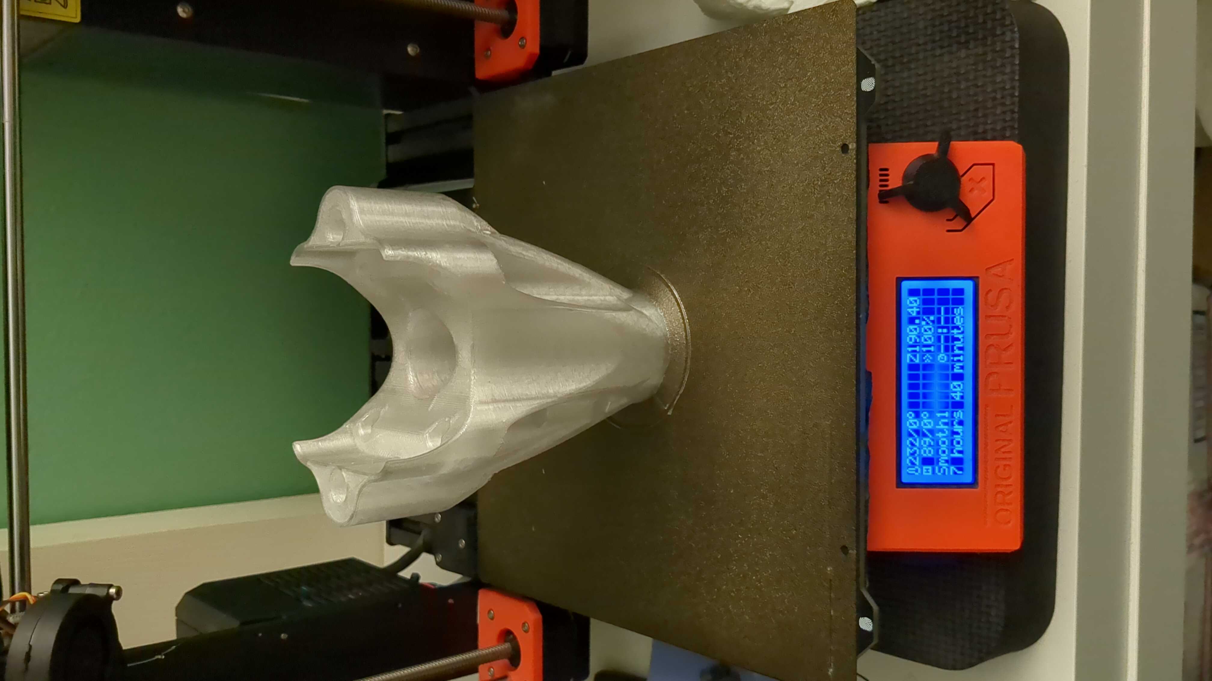
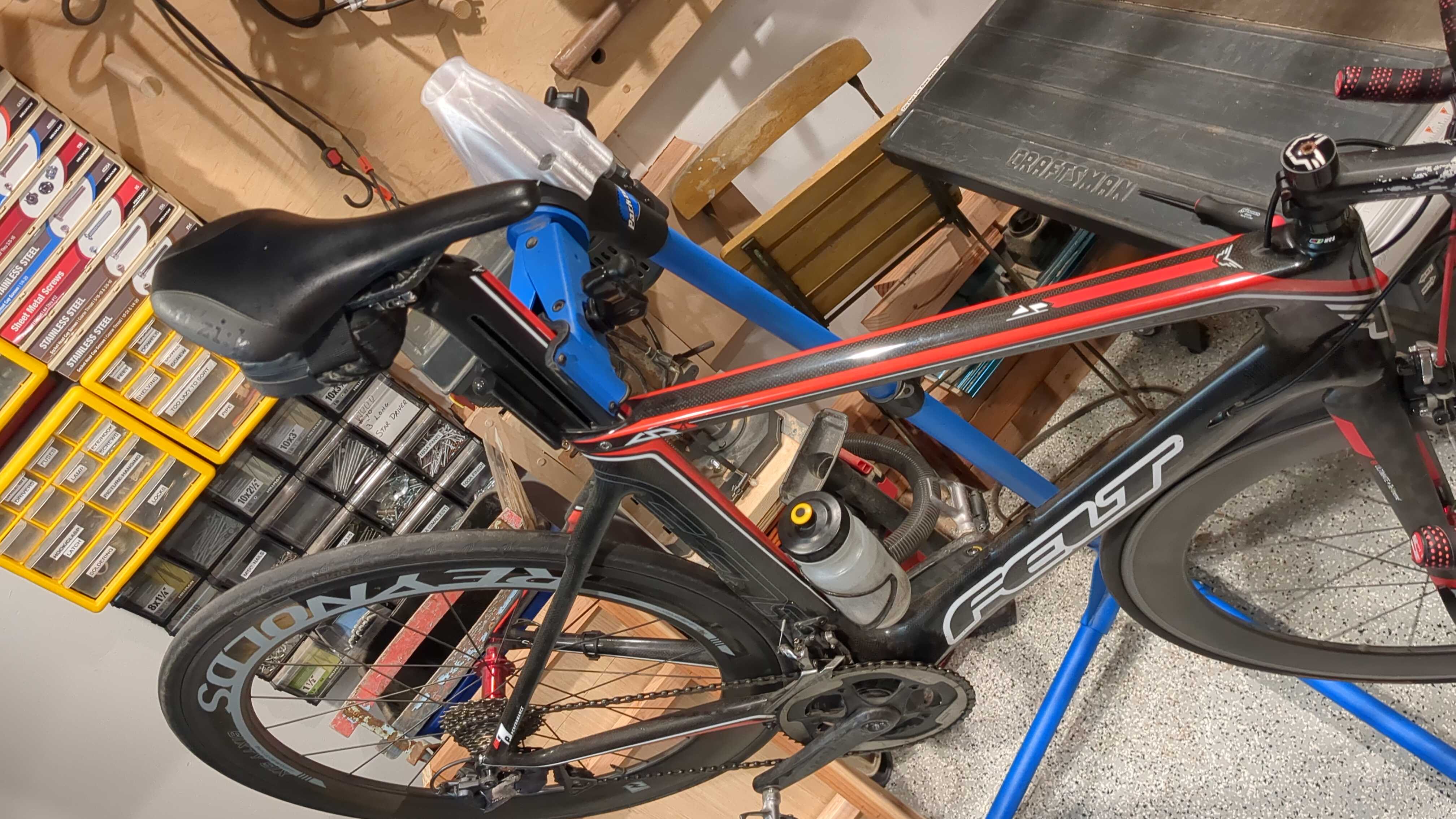
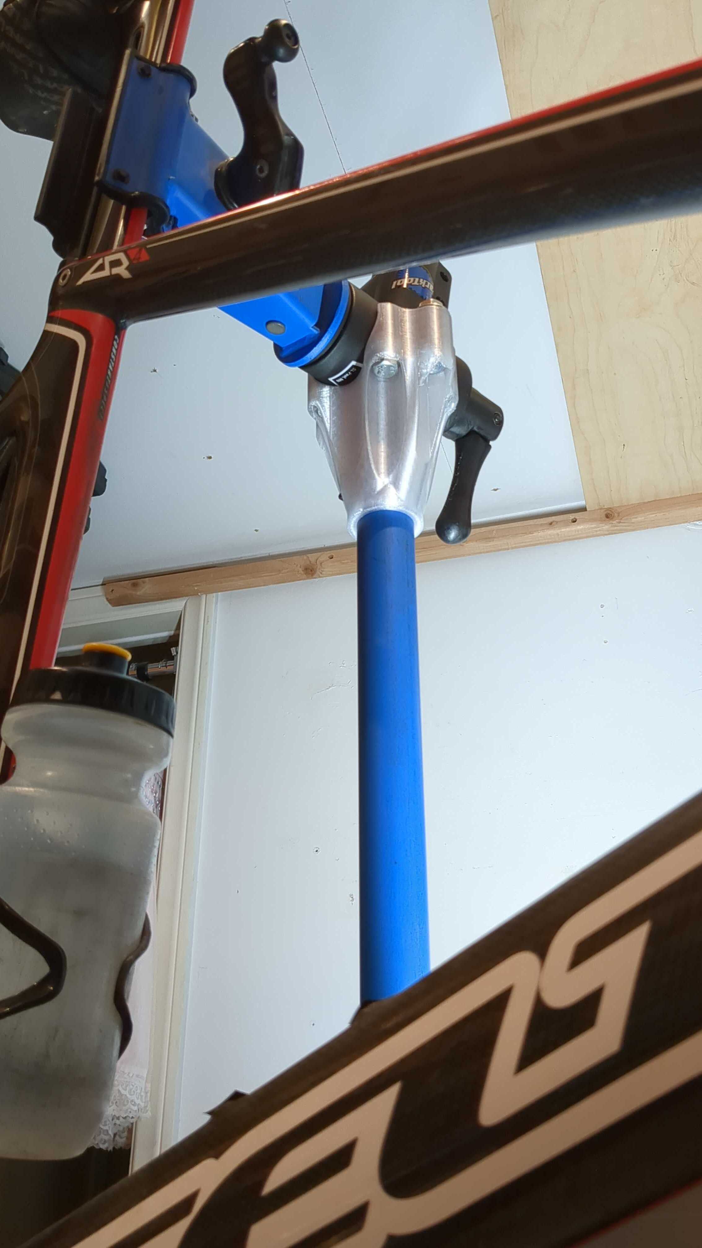
Portable bike stands take up a lot of floor space and suck to deploy and collapse every day. I'm in the process of converting the main stand upright tubes and head to attach to the side of a toolbox cart instead of the base of the portable stand.

Look mah, no supports:

Too much floor space wasted:

I was afraid the pedals wouldn't clear when the head is mounted vertical, but it looks like I still have around 5-10 millimeters of clearance. I still need to design and print the actual clamp mount to the toolbox. This was just a mockup with some wood clamps to check pedal clearance first.

25
88
submitted 1 week ago by j4k3@lemmy.world to c/3dprinting@lemmy.world

https://www.youtube.com/watch?v=x79l7UO_qww

Caveat: The bike used is an e-bike with a powered wheel. The pedals have very little load requirements and no long-term or load testing is shown. As one of the most hardcore roadies you'll ever interact with, personally, I believe this would not last more than a week if it could survive a single ride on a traditional bike and someone like myself based on my first impression of the design. Still, the idea is impressive to me. In practice, a robust enough design will likely outweigh a chain drive by an order of magnitude. The reason the chain and cog transmission is standard is because of the balance of weight to durability. Every single gram matters on a bicycle far more than may be apparent at first.

view more: next ›

3DPrinting

15577 readers
176 users here now

3DPrinting is a place where makers of all skill levels and walks of life can learn about and discuss 3D printing and development of 3D printed parts and devices.

The r/functionalprint community is now located at: !functionalprint@kbin.social or !functionalprint@fedia.io

There are CAD communities available at: !cad@lemmy.world or !freecad@lemmy.ml

Rules

If you need an easy way to host pictures, https://catbox.moe may be an option. Be ethical about what you post and donate if you are able or use this a lot. It is just an individual hosting content, not a company. The image embedding syntax for Lemmy is ![](URL)

Moderation policy: Light, mostly invisible

founded 1 year ago
MODERATORS