15

So last summer, our oven/mw (Whirlpool JQ280) broke (i'm thinking of overheating since it was very hot, but it may as well be electrical default). I tracked down the problem to the motherboard, which has indeed some weldings that burned. I bought a new one and the oven is working again.

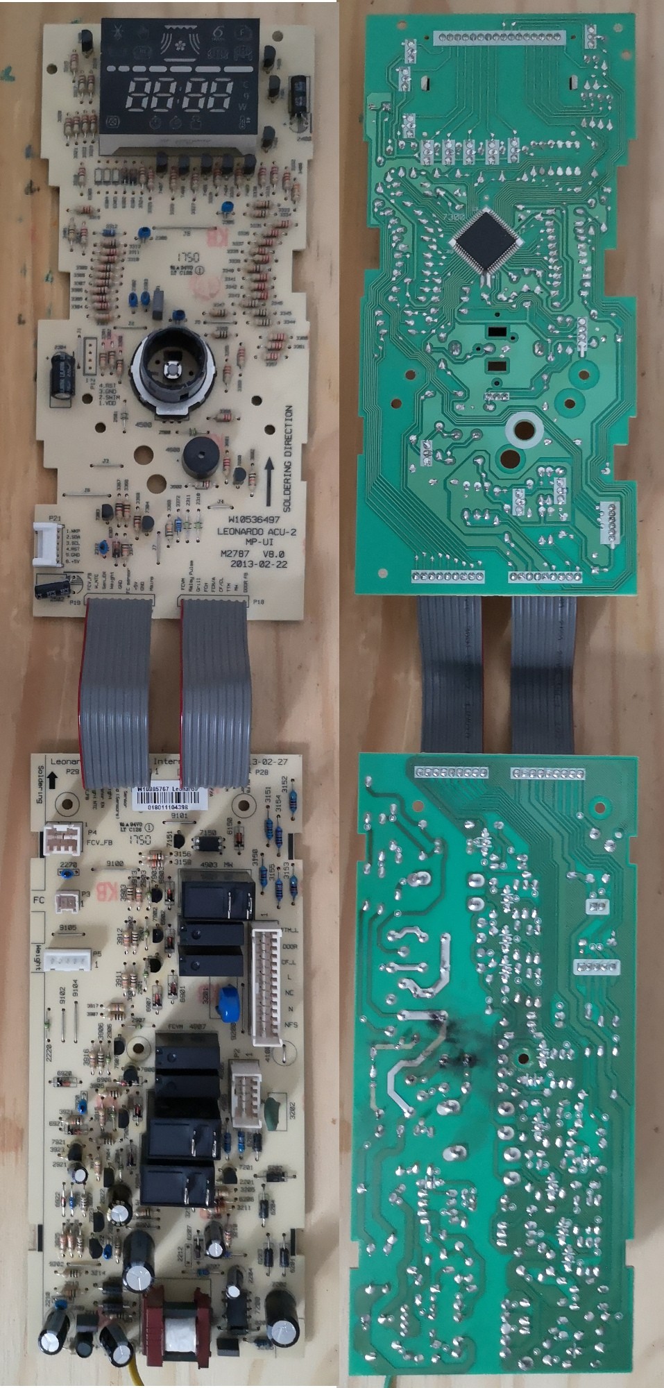
I now have this defective motherboard, separated in two parts. The burned weldings are on the back part, and the front part still has a four-number display, a button and what i assume to be the main chip. I figured that i maybe could get only the front part and make some kind of clock with it.

The easy version would be to feed it 5V current, and if it's not broken it should work as if it was still in the oven, providing a time display. Is there anything dangerous or tricky about that ? I already built/modified a few electrical circuits (spotlights, guitars) but it was always with simple components used for their intended purpose, and i have close to 0 knowledge of electronics. I specifically have no idea if there might be danger of electrical shocks and if it's important to ground it (There are two circuits that are labeled GND on the connection between the two parts, and a yellow/green cable that was connected to the metallic structure of the oven going from the bottom of the back part).

The more complicated version would be to also reprogram the chip, out of curiosity. From Internet, i deduce that it takes some specific hardware to "flash/burn" the chip : either some box in which you put the chip, either some clip that you put around the chip. The problem here is that the chip of this motherboard seems to be 64pins : i think un-welding/re-welding it would be far beyond my welding skills. But on the other hand, it doesn't seem to exist clips adaptators for more than 16 pins. Can you confirm that reprogramming this chip would involve precision welding ?

Anyway, thanks in advance for your feedback, have a great day !

top 15 comments
sorted by: hot top controversial new old
[-] Treczoks@lemmy.world 2 points 1 day ago

If you call soldering joints "welds", then you are probably not the person to attempt this.

[-] Takapapatapaka@tarte.nuage-libre.fr 2 points 1 day ago* (last edited 22 hours ago)

Touché ! Though it may also be a translation mistake, english is not my main language, but reading other comments, i'm getting the vibe that i indeed am not the right person (yet!) to do this kind of stuff.

[-] digilec@lemmy.world 2 points 1 day ago* (last edited 1 day ago)

The easy version would be to feed it 5V current

You could cut or de-solder the ribbon cables and power the upper board alone connecting the +5V and GND wires on the left ribbon to an appropriate power supply. If the upper board isnt blown you might be able to get it to work.

This kind of two board design is quite common. The bottom PCB is a mixed high + low voltage board that includes the mains power supply with bridge rectifier, transformer and smoothing caps. It sends low voltage power to the upper board via the ribbon.

The upper board is entirely low voltage and has a microcontroller, display, buzzer and the control knob. Sensors and switches in the oven are passed over the ribbon to the controller, and control signals are passed back through the ribbon to the relays on the power board which then switch high voltage power to bulbs, fans, and other stuff.

As long as you don't connect it to mains power it's a safe low voltage in this case, there is nothing on this board that will generate high voltage from 5V. Don't leave it powered when you're not there, low voltage can still burn your house down!

The more complicated version would be to also reprogram the chip

This is unlikely, but you never know. Its probably a custom pre-programmed chip that can't be erased, or at the least it has been locked so it can't be modified or have the software read out. It's possible that it could be programmed in place on the board without de-soldering.

Interestingly the upper PCB also seems to have something that looks like an SPI port (P21) it's possible this controls something in the oven but I doubt it. It could be a programming interface but SPI is not typically used for that, maybe a test interface? Hard to say. (edit on 2nd thoughts it probably is a programming interface)

Someone with good electronics / software skills could replace it with an equivalent blank programmable CPU and program it (with something), but that would be a big project even for experienced engineers. Mostly the lack of detailed info about the hardware usually makes it easier to design something new from scratch than to reverse engineer somone elses design.

Those infos are good to know, thank you ! I'll definitely give up any reprogramming attempt x)

For the P21 port, if that interests you or anyone else, the 6 pins are labeled "1.WKP 2.SDA 3.SCL 4.RST 5.GND 6.+5V". After looking at pictures of the dismounted oven, i think it could have been connected to the buttons of the front face of the oven.

[-] digilec@lemmy.world 1 points 1 day ago

WKP - might mean wake up. SDA - serial data out SCL - serial clock RST - reset GND, 5+V - power and ground

Ok so it will be talking to another chip on the keyboard PCB. Not a programming interface.

[-] ragebutt@lemmy.dbzer0.com 4 points 2 days ago

Your more complicated version is untenable for many reasons, the least of which being that I would bet $10 that microcontroller is write protected even not knowing what chip it is (hc11?)

You could drive the display but something on that board blew up. Hard to tell from the pictures but it appears the area around the connector labeled nfs and the black box labeled fcvm 4907 (relay?)

If you simply feed voltage into it it will likely not work. You can get the screen to turn on this way but it won’t function as a clock, something has to send it the logic (that chip). This may still work but you’d have to power the full board and not just the LEDs and the chances are much higher that that burned section has more dead parts surrounding it preventing operation

You can trace to see what’s dead, then try to figure out what killed it, then try to fix it and power the board externally. If that is a relay and the oven was old (or even if it wasn’t and just had shit soldering) the fix could be relatively simple. Relay failure isn’t uncommon on whirlpool boards and cold solder joints are super common on modern appliances. Cold solder joint switching 10-15A at 120-240V will crack/weaken and eventually arc. If you’re lucky it just killed the relay and the fix is easy, just clean the board, swap the relay, fix any cold joints that remain (though it’s less important now that it’s not doing its actual job) and hope that it didn’t destroy a bunch of other stuff when it died

You could also just pull the screen and use it with an arduino or something. You’d have to reverse engineer the pinout but with a screen like that it should be stupid easy to do and that’s actually a pretty good slightly advanced beginner arduino project tbh. Then you could make a custom clock, animate it how you want, etc

[-] mvirts@lemmy.world 2 points 1 day ago

I would post this in an electronics comm

I would have, but the only i found for electronics advices (!askelectronics@discuss.tchncs.de) have no response to the most recent posts, so i figured a more general community would increase my chances at getting advices.

[-] mvirts@lemmy.world 4 points 1 day ago

It may still be worth posting, mostly to reach people who have that com in their home feed.

[-] halfapage@lemmy.world 2 points 2 days ago

Hmm.. For starters, I would recommend you do something a little bit more basic with it for the sake of increasing you knowledge from "close zero". Don't connect mains voltage to it even if it has a connector for that etc..

Playing with the display would be pretty fun. Each section that lights up is a separate LED, so you can imagine that you could light them all up all by yourself if you figure out how they are connected.

You could start with learning about LED polarity, and how to power them without risk of them burning out. After you figure this out, you could then research how microcontrollers (preferably for starters on Arduino format and the like) could let you control them.

I wouldn't recommend trying to use this boards functionality, like taking power from it and such, for now. You could return to that later, armed with more knowledge.

If you do not feel confident with your soldering skills enough to desolder the display, you could cut traces leading to it's terminals to effectively cut it out of the circuit. Those traces look like they would be easy to repair if you wanted to, but for now you could just solder wires to display on board and play with LEDs alone.

What equipment do you have on hand? Any DC power supplies? Multimeter? What kind of soldering iron?

For the chip part, it all really depends. Starting from scratch with one already embedded in an unknown board design with no documentation might be a herculean task even for experienced tinkerers. I would recommend starting small, it really goes a long way.

Thanks for your advice ! I'll give up using the board and just try using the display itself. I have a multimeter and a very cheap soldering iron, with a relatively big tip (smthg like 2mm), but i think it might be enough to desolder the display.

[-] halfapage@lemmy.world 2 points 2 days ago* (last edited 2 days ago)

Using the multimeter you can find out the polarity of each LED. You could use ohmmeter, continuity, or diode mode for that. There are lots of tutorials about how to do that, you can use those keywords to look around. Your meter might not have all those modes available, you have to check and use one of them.

A bit of advice about LED in displays like those: either some of them or even all of them might have one "side" of polarity tied together. Like, all cathodes or anodes might be internally connected together just for the sake of reducing the count of terminals, and therefore traces on the board. Look out for this if something doesn't make sense while you look for individual diodes.

Do you have an idea for providing, say, 5VDC?

Do you have soldering flux and some way to wipe the tip if it gunks up?

Thanks for the tips, it seems my multimeter has all those mods.

For providing current, i'll look around me, maybe my parents have a power supply or i can get one. Otherwise i'd probably buy a 5V adapter, and use pigtails cables that i have from previous projects to connect everything.

For soldering, i use absolutely no flux, and wipe the tip on a slightly wet old sponge. I guess this is quite a bad setup, but i have very little use of it.

[-] TheFrogThatFlies@lemmy.world 1 points 1 day ago

Why not replacing damaged components and use it as a backup in case the new one breaks?

Well that's a good option too, and probably what i'll do, since people convinced me to not try to play with the board itself. I would get help to do this though, because that's way beyond my skills, and while i'm relatively confident in trying to play with circuitry and digital display, i'm far less confident when it's about stuff that cooks things at 200° x)

this post was submitted on 01 Aug 2025
15 points (100.0% liked)

techsupport

2917 readers
1 users here now

The Lemmy community will help you with your tech problems and questions about anything here. Do not be shy, we will try to help you.

If something works or if you find a solution to your problem let us know it will be greatly apreciated.

Rules: instance rules + stay on topic

Partnered communities:

You Should Know

Reddit

Software gore

Recommendations

founded 2 years ago
MODERATORS